A while ago I picked up these VQB71 seven segment displays.


A while ago I picked up these VQB71 seven segment displays.
Following on from my previous post where I looked inside a cheapo battery charger from eBay – I have since gutted the charger. All that I kept was the case and the battery contacts.
Gutting the unit eliminates a potential fire hazard. I replaced the circuitry with a dedicated lithium ion battery charger IC instead.
I’m using a MAX1555 and it is a single chip solution which requires a minimal number of external components. It is a single cell charger and has a maximum charge current of 280mA.
The chip has dual inputs, allowing you charge a battery from either a USB port or a DC plug pack. When charging from a USB port, the charge current is limited to 100mA. Whereas, the DC plug pack input allows for a charging current of 280mA. Also, this version of chip has a charge status indicator which can be used to drive an LED.
I’m not going to use the 240VAC socket anymore, and I’ve replaced it with a micro USB socket. This change lets me use a USB wall socket adapter which can deliver 1500mA at 5VDC. However, my new circuit will only require 280mA. (I’m already thinking about a 2nd iteration of this project which will use an IC with a higher charger current to charge faster.)

Its amazing how cheap some stuff is on eBay these days.
For example, I picked up 3x lithium ion batteries and a charger to suit my Olympus TG-4 camera for $25 Aussie dollars, including free delivery.

I have an upcoming camping trip and I wanted to get some spare batteries for the camera.
I didn’t want to buy just 1 battery in case it was dead on arrival so I got 3. The battery charger was a bonus. Olympus don’t supply a proper battery charger when you buy a TG-4, you have to charge the battery in the camera with a USB charger and charge times are pretty slow. Olympus sells an AC powered charger but its about $70 and doesn’t include extra batteries. I was hoping that the new charger would be faster or reasonably good, but I didn’t have high hopes on the quality of the battery charger.
Two screws at the back of the charger were removed, but the plastic halves are ultrasonic welded together. Splitting the ultrasonic weld was very easy though. A bare minimum of plastic has been used and it isn’t very rugged.

Just a quick update. I was going through some boxes that I haven’t unpacked since moving and I found the linear CCD I was experimenting with.
After reviewing some schematics I’d saved and reviewing some datasheets, I’m sort of back up to speed with where I left the project.
I managed to get some traces on my analogue oscilloscope that sort of match the datasheets but the relatively fast timings and the inability to store a trace on my oscilloscope was making things difficult. So, I took the board into work to use one of the good digital oscilloscopes in the workshop and I managed to get the following trace.

After performing a few tests I am not confident that I have all of the signals or the timing correct. Why I know this is because when I placed small pieces of black tape over the CCD’s lens, I was not seeing a decreases in signal intensity to match the number of pieces of black tape. Also, when I shaded a quarter of the CCD, the signal output for all the CCD’s pixels decreased in output value rather than the pixels that were shaded.
Anyway, I’m learning a few things about analogue electronics which is good. So far I’ve needed to improve my knowledge on op-amp circuits and I’ve been using a sample and hold circuit to help isolate the specific pixel output signal from the entire output waveform.
Anywho, I’m sure I’ll share more details as they arise.
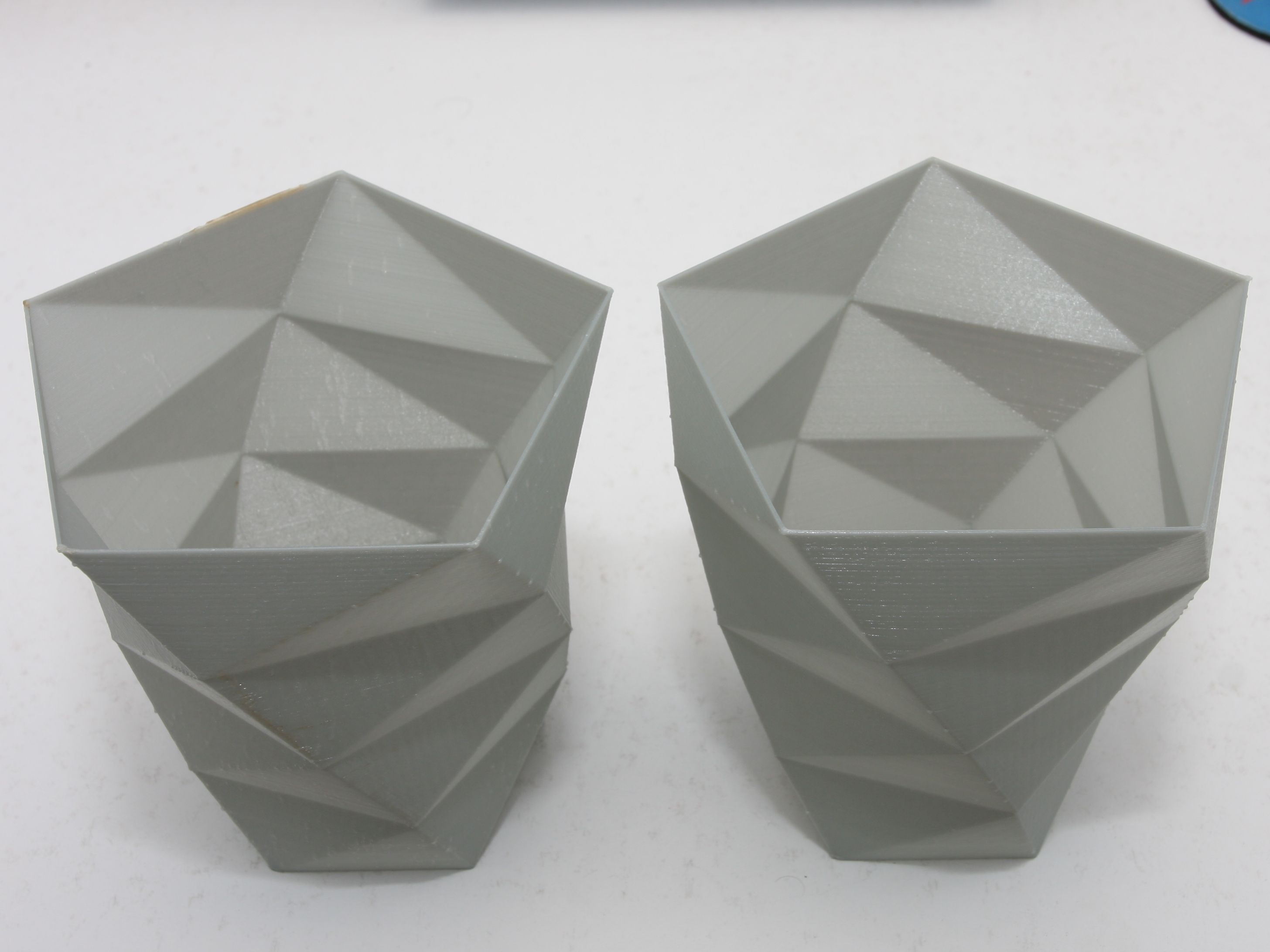
Just a quick update as I still continue to enjoy using PETG.
Recently I had a go at testing how PETG goes when printing in vase mode.
This weekend just gone I visited the Powerhouse Museum in Sydney. Currently, there is an exhibit of several Egyptian Mummies from the British Museum’s collection. The exhibition wasn’t too bad and there were plenty of amazing bits and pieces on display. (The British Museum has “acquired” quite a collection of Egyptian antiquities).
Personally, I don’t quite get the appeal or understand the need to know such excruciating detail about how these people lived and died 3000 years ago, but its not everyday you get to see something that old. (Will people in 3000 years really care so much about how we are currently living?) Anyway, entry into the exhibit also gave access to the rest of the Museum.
If you’ve never been to the Powerhouse Museum, its Sydney’s museum dedicated to technology and applied science. I’d recommend visiting the museum if you’re ever in Sydney. If you’ve stumbled across this website, then I’m sure you’d be interested in the museum’s exhibits. Continue reading
So far its been almost two weeks since I started using PETG and I’ve resolved a lot of the problems I was experiencing in my last update.
My prints are no longer becoming completely stuck to the print bed. Now, I can easily peel the completed print from the bed once it has cooled to about 45°C. Removing the print is almost trivial in how easy it is to do.
To achieve this, the first layer settings are very different to that of ABS. Smearing the filament into the bed is the wrong approach. It leads to nozzle jams and adhesion that causes the print to break. Instead, I have found that a first layer height of 105% of first layer thickness is needed. The extruded filament literally is laid down onto the bed. It looks as if it has no chance of adhering, however it is working perfectly.
After waxing lyrical previously how I’d fixed my nozzle jams by increasing the first layer height and reducing print speed, nozzle jams returned. They became quite significant. I was about 50% of the way into a print when they began occurring and I tried to salvage the print. Each time a jam occurred, I’d pause, remove the filament, cut the damaged filament off and insert it again and continue on. Continue reading
I haven’t done a teardown in a while so I thought I’d share the insides of panel meter I recently found at a Sunday morning junk market for $5.
Below is a panel meter that has been used in some sort of industrial process. It was manufactured in 1980 by Kuwano. I’m not quite sure who the manufacturer was – the company’s logo is not easy to read but it might say, “Aumano”. What caught my attention with it was that it includes high and low needles as well as indicators and relay outputs for the high and low limits.
It’s been just over 1 week since I started using PETG instead of ABS.
I am very impressed with its performance. There have been a few print problems, however I have managed to identify and rectify some of these problems. Continue reading

