

Introducing the MicroLogix 1400 PLC (1766L32BXBA) from Allen Bradley.
A PLC – Programmable Logic Controller – is a device that is widely used in industry for controlling electro-mechanical processes. They are a different beast to your Arduino – you don’t get much change from $1500 for this model PLC – being that they are more robust in construction and flexible to program (PLC ladder logic or statement list programming is a different approach than using a language such as C).
This model is considered a ‘shoebox’ PLC due to its size being about the size of a ‘shoebox’. It is by no means the largest or most powerful PLC that you’ll find but it is definately not a slouch for small to medium automation tasks.
A quick rundown on this device’s specifications;
- 24VDC power input
- 24x inputs – 20x digital and 4x analogue
- 14x outputs – 12x digital and 2x analgoue
- A combination of relays and FETs for the digital outputs
- 12bit analogue input and output resolution
- Each digital output channel can individually drive 2.5A
- Individual ethernet and RS-232 communications ports
- Input and output expansion cards can be added
- A programmable LCD
- Is fully operational when subjected to -20 to 60C temperatures

Today’s candidate had an unfortunate encounter with 240VDC on its 24VDC inputs and 5 of its 20 digital inputs are fried, but we’ll get to that later.
Removing all the front covers reveals the screw terminals, a programming port (bottom left), backup battery and expansion card port on the right.

Once all screws are removed, the front faceplate easily lifts off revealing the input and output interface board. A large pin connector on the right connects the IO interface board to the front panel.

The front faceplate separates from the PCB and includes the LCD. Not much interesting to see with the LCD.

Lets take a look at the main control board and already there are several serious looking ICs.

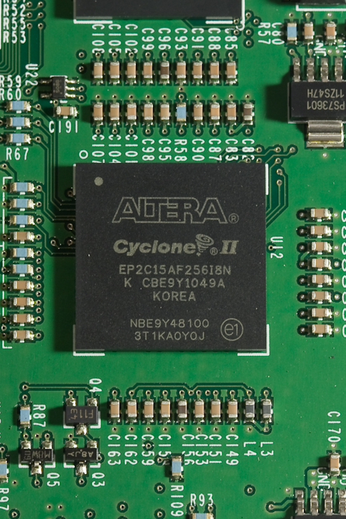
Taking a close look at the large PCB reveals that this is where all the grunt work takes place. The hardware for this PLC was probably designed about 5-6 years ago – the date stamps for the ICs suggest their manufacture was in 2010. Onboard is an Altera Cyclone 2 FPGA and this is where I expect the user’s logic is executed. An FPGA would allow the user to include many more hardware based timers, counters and math operations than is possible with a microcontroller or microprocessor.
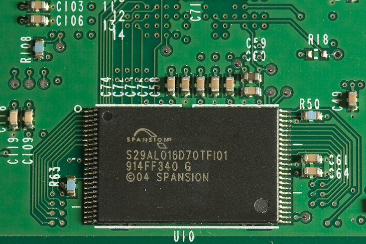
Located underneath the FPGA on the other side of the PCB is 16Mbit of Flash memory. This would be where the FPGA’s bit file resides and is loaded from each time the FPGA is reset.
Additionally there is a Freescale ColdFire MC5275 microprocessor. A quick check of this device’s datasheet reveals that it is a respectable piece of hardware. My thoughts are this is the device that performs the overall operation of the hardware, where your programming PC interfaces to when monitoring, loading new ladder logic or performing ladder logic online edits. Your new PLC code would some how pass through this device before it is executed in the FPGA. The upper right chip is 8Mbit of SRAM and the below it is a further 16Mbit of SRAM both manufactured by Cypress.

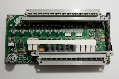
The IO interface is handled with the following board. The 2x white ICs are opto-isolators manufactured by Toshiba and used for regular digital inputs. Each of the 6x 8pin black packages to the left interface to PNP transistors above them. I can’t find details on the 8pin package but, these would be the remaining 12 “fast” digital inputs. 6 relay outputs can be seen and squeezed between the relays and covered in the grey rubber glue compound are 6x DC outputs. In the bottom right hand corner are ICs from Analog Devices and these provide the analogue input and output interface. All the signals’ status is piped through the large pin connector on the right hand side.
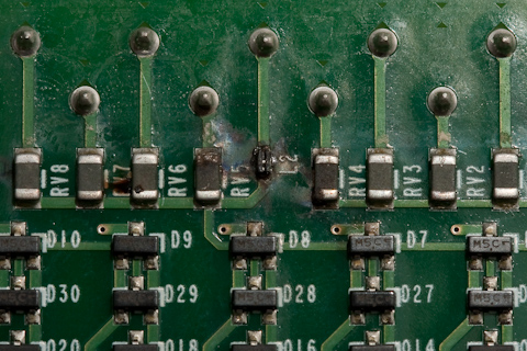
On the reverse, there is more hardware that appears to pre-condition the digital input signals.

The damage from placing 240VDC on the 24VDC inputs can be seen. Only one channel was actually subjected to the overvolts, but it has resulted in damage to 5x of the digital inputs. When time permits, I’ll trace out the input conditioning hardware and try to learn some useful design tips – there is probably some sort of bridge rectifier implemented.
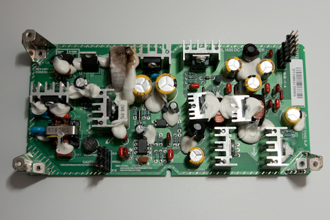
Finally, to power the whole unit, there is a dedicated power supply board. This was more substantial than I expected and looking at the silkscreen markings there are 3.3V, 5.2V and 24VDC supplies being generated. The 24VDC supply appears to be capable of 5A continuous going by the markings. Interestingly, it looks as if the design of the power supply has been outsourced as it is marked Dong Yang E&P in the bottom right hand corner. Note the brown flashover marking on the inductor to the left of the yellow electrolytic capacitor.
A final rundown on the more notable pieces of hardware:
- Altera Cyclone 2 FPGA – EP2C15AF256
- Freescale ColdFire microprocessor – MCF5275
Well that’s it. Overall some nice pieces of hardware and a good chance to take a look inside a medium-range PLC.

Hi,
I am interested in the teardown of this device for the information you provided but also am curious about the analog input section — what specific ICs were used (you indicated there were from Analog Devices) and what type of input filtering or input protection is on the board.
Thanks!
LikeLike
Hello During removing the memory module from plc it’s come out along with base and getting error 0006t please guide how to resolve the issue.
LikeLike
Hii
I have also received the same plc for repair having same fault please suggest me how i can i repair the plc.
Thanking you
LikeLike