
Overview
With a handful of components and access to a 3D printer, you can make your own homemade weather station. You’ll always know the temperature and relative humidity at a glance.
For this project, an Arduino samples an HTU21D temperature and humidity sensor and displays both results on a 24 LED NeoPixel ring. To protect your HTU12D breakout board, we’ll be installing the sensor inside a mini 3D printed Stevenson Screen.

Required Components
Electronic components
- 24 LED Neopixel ring
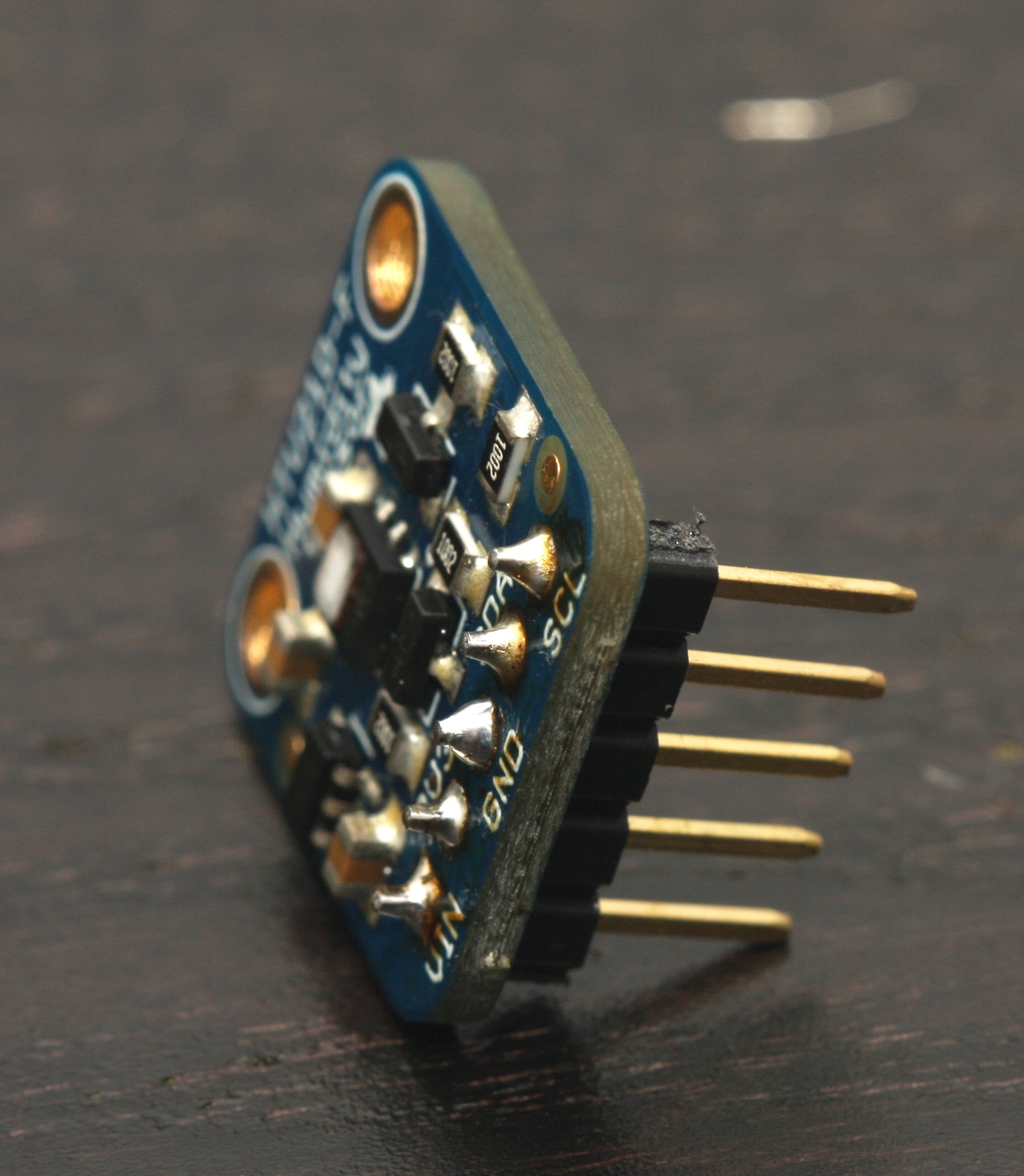
- HTU21D humidity and temperature breakout – The housing has been designed to suit the the HTU21D breakout from Adafruit
- Arduino Pro
- 5V power supply
- Pin headers
- 2 pin Molex connector
- 3 pin Molex connector
- Computer cable with a minimum of 4 cores
- Solder
Other components
- White ABS filament
- 1x cable gland with 12mm thread
- 2x 3mm screws to suit
- Heatshrink
Required Tools
- Safety glasses
- Access to a 3D printer (expect about 6 hours of print time)
- Diagonal cutters
- Pointy nose pliers
- Flat blade screwdriver
- Phillips head screwdriver
- Soldering iron
- Drill bits for pilot hole and to suit cable gland
- Cordless drill
- Stanley knife – be careful of the sharp blade
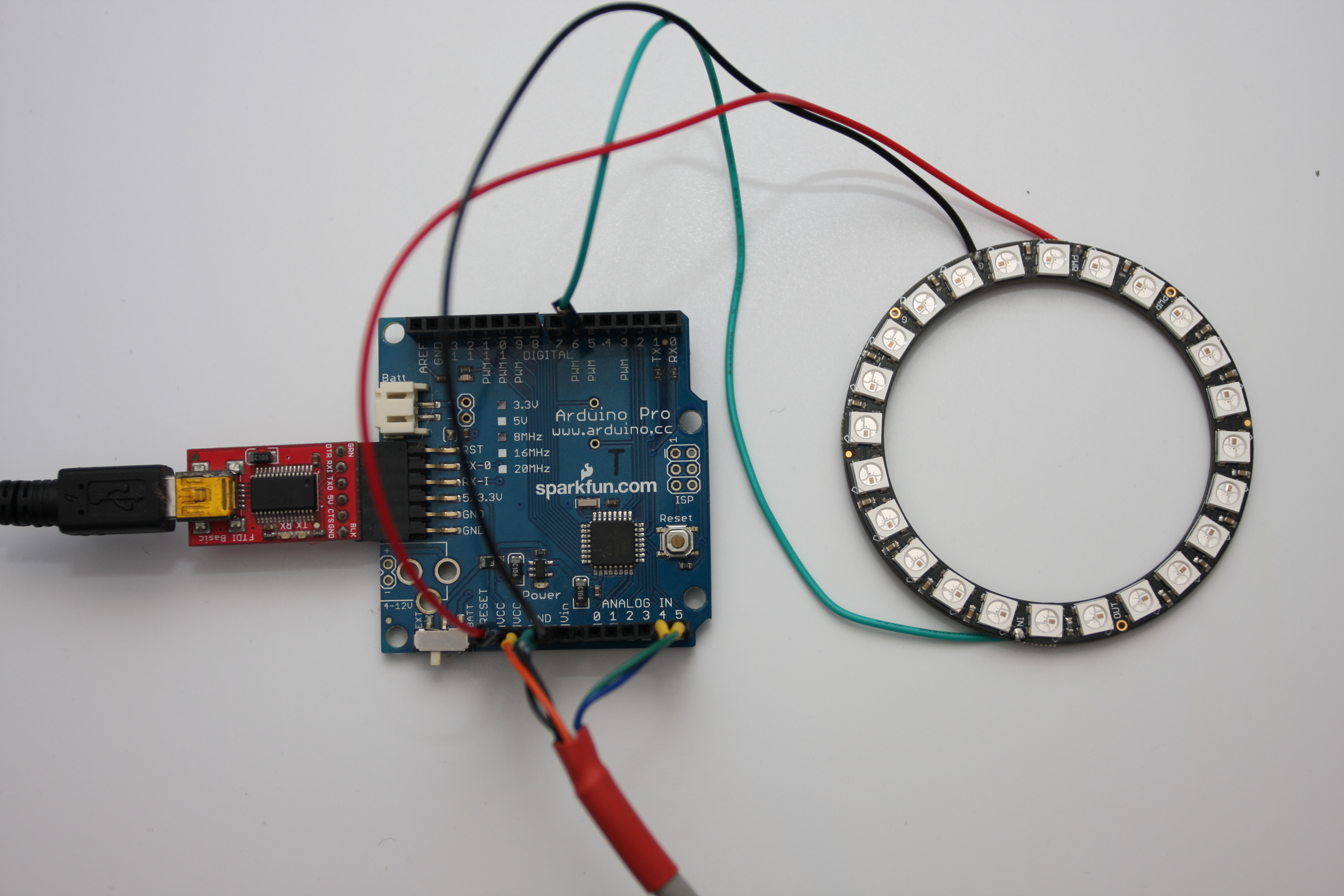
Wiring
This is a straightforward circuit to wire.
(Note that the wiring diagram shows an alternate HTU21D breakout board. The Adafruit breakout’s additional 3V3 pin is not shown but it is not required.)

Connections
| Arduino | HTU21D | NeoPixel Ring |
|---|---|---|
| VCC | VIN | Power +5V |
| GND | GND | GND |
| A4 (SDA) | SDA | |
| A5 (SCL) | SCL | |
| D6 | Data Input |
Power Supply
Power for the circuit will be provided by a FTDI Basic breakout connected to the programming port. The USB lead for the FTDI Basic will then be plugged into a USB wall adapter.
However, you could use a large capacity LiPo battery or 9V wall adapter.
3D Printing
The latest model files are available for download from Thingiverse.

This model requires support material for the main body of the Stevenson Screen. Supports allow the main body to be printed in one complete piece ensuring strength and durability whilst outside.
To cover the model, there is a small lid that has tabs which align with notches in the top of the main body. Twist the lid to lock it into position.
The stand that has an 18mm internal hole that allows the Stevenson Screen to be attached to a post.
The body sits on the stand with a press fit, but a few dabs of Super Glue area good idea.
Recommended Print Settings
- Material:White ABS
- Infill: Moderate to high to achieve good rigidity.
- Speed: Normal
- Shells: Thick
- Supports: Required for the main body and support stand.
Stevenson Screen
Long pointy nose pliers and a flat blade screwdriver are recommended to remove the support material.


Stand
Again, pointy nose pliers are good at tearing off the support material.


Lid
Not much to say really.

TOP
Assembly
Soldering HTU21D Breakout
Solder 5 male pins to the HTU21D breakout board with the solder connection made on the component side of the breakout board.
Soldering NeoPixel Ring
I chose to cut up some male header wires. Install a red wire in the “PWR +5V” terminal, a black wire in the “GND”terminal and a wire in the “Data Input” terminal.


Install Cable Gland
Invert the Stevenson screen and choose a suitable position for the cable gland. Make sure it doesn’t obstruct the stand and is not too close to the edge. Mark the centre with a permanent marker.
Use about a 4 mm drill to make a pilot hole. Then use a drill with the same diameter as the cable gland’s thread to make the final hole.
Press the cable gland into the hole with a twisting motion to secure the gland in position. The cable gland’s lock nut isn’t necessary.


Terminate Cable at Stevenson Screen End
Prepare cable
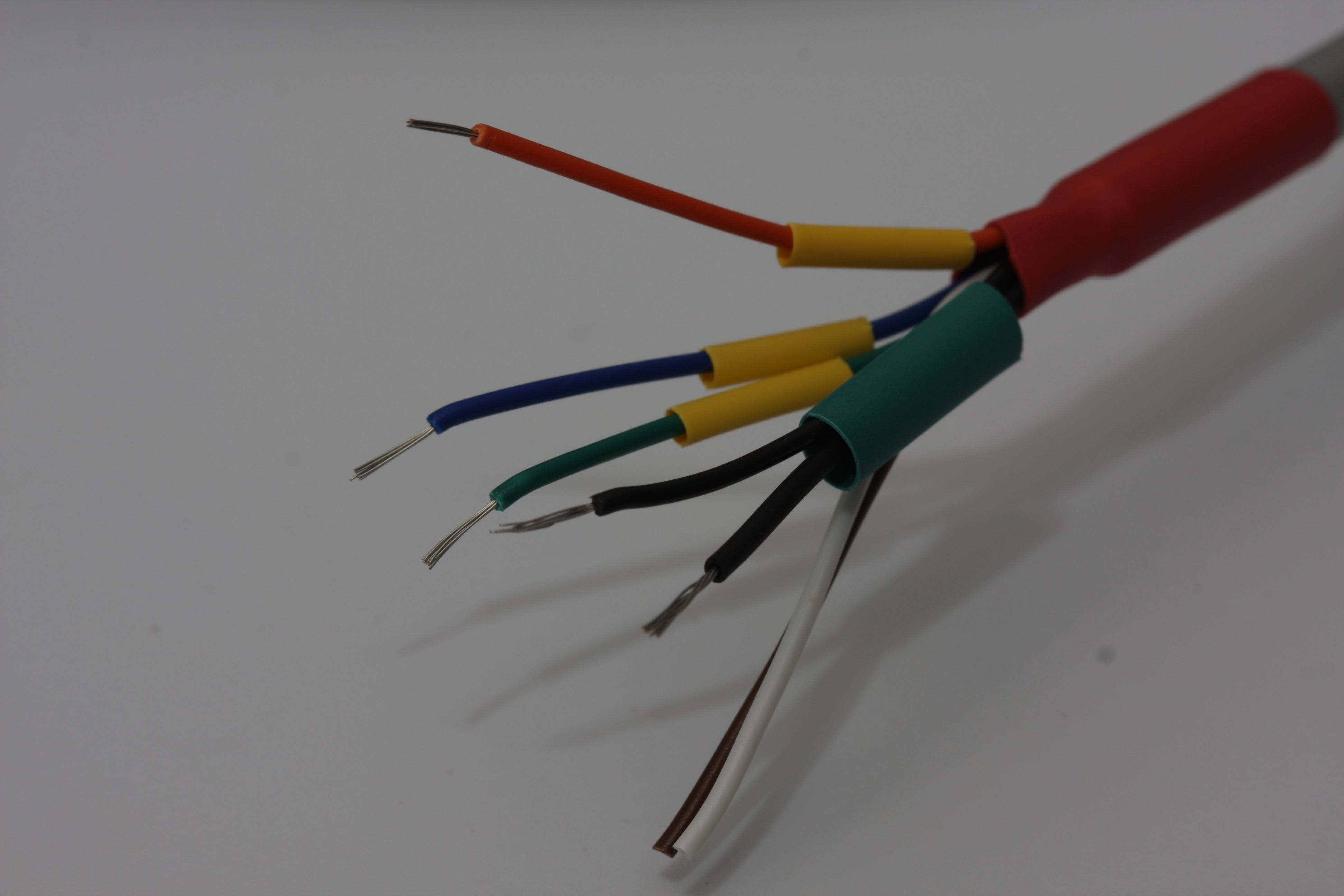
Pull about 500mm of the computer cable through the cable gland. Then using a sharp knife, carefully strip about 100mm off the outer layer insulation. If your cable has a shield wire, cut it off flush with the cut insulation, the shield wire isn’t necessary at this end. Install some heatshrink over the cable where the insulation has been removed to make the job look tidy.


Terminate Cable
Only four wires are required so decide on the colours that you’ll be using. Strip off about 5mm of insulation. Before terminating the Molex connectors, trim the conductor to the correct length. One set of crimp tabs are for securing the connector to the insulation. The other crimp tabs make the electrical connection. The connector carrier strip can be removed with small cutters.


Insulate Unused Cores
This step is not necessary if your cable only has 4 cores. Unused cores should be insulated from the elements in the event that you may want to use them in the future. Place some short lengths of small heatshrink over the cores, heat the heatshrink and whilst it is still warm, gently crimp the heatshrink with some pliers.


Insert Connectors into Molex Sockets
Once all the 4 Molex connectors have been crimped, insert each connector into their plug. Gently pull the cable back through the cable gland and tighten the gland.


Install HTU21D Breakout Board
Using 2x short 3mm screws, secure the HTU21D to the standoff inside the Stevenson Screen. Firmly twist the screws in so the screw’s thread bites into the plastic. Ensure the wires aren’t squashed by the Molex plugs.


TOP
Terminate Cable for Arduino End
My Arduino Pro has female pin headers installed, so, to terminate the computer cable, male pin headers will be used.
Prepare Cable
Carefully strip back about 100mm of outer insulation with a sharp knife. Remove any foil shielding. This time, keep the shield wire and insulate with heatshrink. Cover the cut outer insulation with heatshrink for tidiness.


Prepare Wires
Strip back about 5mm of insulation from the four wires that you are using. Slide heatshrink over the individual wires. I grouped the black wire (GND) and the shield wire together as they will be soldered together.
Solder Wires to Header
Using 2 small pieces of Blue-Tac, position the header the wire conductors close to each other. Solder the wires to the header.


Finish Connectors
Slide the heatshrink down and shrink. Then using some cutters, separate the header.


TOP
Wire up HTU21D, Neopixel and Arduino
Connect up all the components as per the wiring diagram.
Install Housing
Ideally, you should install the Stevenson Screen in a location that is free of shade from trees and buildings to ensure quality data. I’m limited with locations where I can install my sensor. I’ll forego my weather measurements being scientifically correct, I really just want to know the temperature and humidity.

TOP
Software
Most weather stations display the numerical values of the conditions being monitored. However, for this weather station, both temperature and relative humidity are displayed simultaneous on a 24 LED NeoPixel ring.
Temperature values are ranged between 12 to 36 degrees Celcius and are displayed in red. Whilst relative humidity values are shown for the full 0-100% range in blue. Both temperature and humidity are shown together on the NeoPixel ring.
The humidity readings are temperature compensated as per the equation provided in the HTU21D datasheet. All calculated measurements are output on the serial port too.
This software utilises the Adafruit NeoPixel library which you can get download and get details on how to use by following their guide.
Once the NeoPixel library is installed, copy the code into a new sketch and compile. Don’t forget to select the correct Arduino board and processor type.
//Code to read the temperature and humidty from a HTU21D temperature sensor and display it on a 24 LED NeoPixel ring.
//Tim Hansen 20/4/15 - www.steelcityelectronics.com
//HTU21D
//Protocol: I2C (TWI)
//Specs - Temperature: -40 to 125 degrees Celcius
// - Humidity: 0 to 100% relative humidity
// - Voltage: 3.8VDC max
//NeoPixel ring
//LEDS = 24x

//What libraries do we need?
#include <Wire.h> //The "Wire.h" library is required to use the I2C commands
#include <Adafruit_NeoPixel.h> //This project requries the use of the Adafruit NeoPixel library
 //Checkout https://learn.adafruit.com/adafruit-neopixel-uberguide/arduino-library for details

// Which pin on the Arduino is connected to the NeoPixels?
#define PIN 6

// How many NeoPixels are attached to the Arduino?
#define NUMPIXELS 24

// When we setup the NeoPixel library, we tell it how many pixels, and which pin to use to send signals.
Adafruit_NeoPixel pixels = Adafruit_NeoPixel(NUMPIXELS, PIN, NEO_GRB + NEO_KHZ800);

void RequestMeas(int Address, int CommandCode)
{
 Wire.beginTransmission(Address); // The HTU21D will respond to its address
 Wire.write(CommandCode); // request the measurement, ie temperature or humidity
 Wire.endTransmission();
 return;
}

long ReadMeas(int Address)
{
 //A measurement from the HTU21D is returned in 3 consecutive bytes. See page 11 of the datasheet
 //the order of returend data is: [DATA (Most Sig Byte)], [DATA (Least Sig Byte)], [Checksum]
 //We will ignore the checksum to save computation time and complexity. Page 14 of the datasheet details how to calculate the checksum

 byte DataHIGH; //The location to store the high measurement byte
 byte DataLOW; //The low measurement byte
 byte CRC; //If you want to compute the CRC feel free to do so.

 long Data; //The temporary memory location we are storing our data in as we receive it from the HTU21D
 //Each packet of data is only 8bits in length, but if we do a bit shift we can store the 2 packets of
 //measurement data in a variable. Remember you can only return 1 variable when a function finishes.
 //Ideally, we'd use an int to store the result, however, at high measurement values in 14bit mode, an int overflows.
 //To prevent overflow, we must use a single long (32bits).

 Wire.requestFrom(Address, 3); //We are requesting data from the HTU21D and there will be 3x bytes that must be read.
 while(Wire.available()) // Check for data from the HTU21D
 {
 DataHIGH = Wire.read(); // Read high byte
 DataLOW = Wire.read(); // Read low byte
 CRC = Wire.read(); // Read the CRC byte
 }

 //OK, so now we are going to 'pack' our 2x bytes of data measuremetns into a single int so only 1 variable is returned.
 //To do this, we will use the left bitshift operator '<<'. What this does is push all the bits across to the left.
 //FUN FACT: performing a left bit shift is equivalent to multiplication by 2 for each shift. The reverse is true for right
 //bitshift which is equivalent to dividing by 2. This is a more efficient method to perform multiply or divide by 2.

 Data = DataHIGH; //The data sits in the low byte of 'int Data'.
 //Ie, Data = [00000000][00000000][00000000][8 bits of DataHIGH]
 Data = Data << 8; //Shift all the bits to the left for 8 bits. The old locations fill with zeros.
 //Ie, Data = [00000000][00000000][8 bits of DataHIGH][00000000]
 Data = Data + DataLOW; //Now simply add the low byte of data to the int.
 //Ie, Data = [00000000][00000000][8 bits of DataHIGH][8 bits of DataLOW]

 return Data; //return our measurement.
}

void setup()
{
 Wire.begin(); // join i2c bus (address optional for master)
 Serial.begin(9600); // start serial for output
 pixels.begin(); // This initializes the NeoPixel library.
}

void loop()
{
 //Set the address of the HTU21D. This detail is hidden at the bototm of page 10 of the datasheet.
 const int I2C_address = 0x40; // I2C write address. Note that 'const' has been declared. If you try to write to this variable
 // anywhere else in your code you'll get a compilation error. This prevents you from doing silly things.

 const int TempCode = 0xE3; // A temperature measurement is executed with this command code. See page 11 of datasheet.
 const int HumidCode = 0xE5; // A humidity measurement is executed with this command code. See page 11 of datasheet.
 const float TempCoefficient = -0.15; //The temperature compensation coefficient value to guaratnee RH accuracy between 20-80%RH

 long Temperature; //Perform our calculation using LONG to prevent overflow at high measuremetn values when using 14bit mode.
 long Humidity;

 float TemperatureFL; //Variable to store our final calculated temperature measurement
 float HumidityFL;
 float HumidityCompFL; //%RH value that has been temperature compensated to gurantee performance of +-3% between 20-80%RH

 byte const BaseBrightness = 10; //Set the brightness of the LEDs. The highest measurement reading will display this brightness
 byte const ColourBoost = 20; //The lower measuremetn reading needs to be 'boosted' otherwise it gets swamped by the the other higher reading.

 byte TempScaled; //Variable to hold the scaled temerpature valeu
 byte TempMin;
 byte TempMax;
 byte HumidityScaled;

 delay(100); // a short delay to let everything stabilise

 while(true) // execute all the instructions in this loop forever
 {
 delay(10); //add a small delay to slow things down

 RequestMeas(I2C_address, TempCode); //Request the current temperature
 Temperature = ReadMeas(I2C_address); //read the result

 //We must now convert our temp measurement into an actual proper temperature value
 //According to page 15, the conversion equation is: Temp = -46.85 + 175.72 x TeampMeas / 2^16
 //Becasue the result will have decimal places in the result we must use a Float datatype.
 TemperatureFL = -46.85 + 175.72*(Temperature/pow(2, 16));

 delay(10); //add a small delay to slow things down

 RequestMeas(I2C_address, HumidCode); //Request the current humidity
 Humidity = ReadMeas(I2C_address); //read the result

 //We must now convert our humidity measurement into an actual proper humidity value
 //According to page 15, the conversion equation is: Humidity = 6 + 125 x TeampMeas / 2^16
 //Because the result will have decimal places in the result we must use a Float datatype.
 HumidityFL = -6 + 125*(Humidity/pow(2, 16));

 //The relative humidty value read from directly from the chip is not the optimised value.
 //We must perfrom the 'temperature Coefficient Compensation Equation" specified on page 4 of the datasheet
 //RHcompensated = RHactual + (25 - TEMPactual) * coefficient
 //The coefficient value is -0.15%RH/C - from page 3 of datasheet
 HumidityCompFL = HumidityFL +(25 - TemperatureFL) * TempCoefficient;

 //All the calculations are complete, lets now display our values for temperature and humidity on the serial port.
 Serial.print("Temperature: ");
 Serial.print(TemperatureFL);
 Serial.print("C");

 Serial.print("\t");
 Serial.print("Humidity (raw): ");
 Serial.print(HumidityFL);
 Serial.print("%RH");

 Serial.print("\t");
 Serial.print("Humidity (Comp): ");
 Serial.print(HumidityCompFL);
 Serial.println("%RH");

 //scale temperature
 //temp range is 12C to 36C
 //Make 1 degree equal 1 pixel. Therefore set a minimum temperature and then add 24 pixels to it.
 TempMin = 12;
 TempMax = TempMin + 24; //think about a better way to do this for smaller neopixel products

 TempScaled = byte(TemperatureFL);
 TempScaled = TempScaled - TempMin;

 HumidityScaled = byte(HumidityCompFL)>>2; //divide by 4. each right shift is equivalent to a divide by 2.

 //drive the neopixel ring
 for(int i=0;i<NUMPIXELS;i++)
 {
 if(i<= TempScaled)
 {
 if(i<= HumidityScaled)
 { //Set the temperature and humidity coloured pixel
 //pixels.setPixelColor(i, pixels.Color(10,0,10)); //temperature pixels are red, humidity pixels are blue
 if(TempScaled == HumidityScaled)
 {
 pixels.setPixelColor(i, pixels.Color(BaseBrightness,0,BaseBrightness)); //temperature pixels are red, humidity pixels are blue
 }
 else if(TempScaled >= HumidityScaled) //boost the humidity pixels so they can be seen more easily
 {
 pixels.setPixelColor(i, pixels.Color(BaseBrightness,0,BaseBrightness + ColourBoost)); //temperature pixels are red, humidity pixels are blue
 }
 else //Boost the temperature pixels so they are more easily seen
 {
 pixels.setPixelColor(i, pixels.Color(BaseBrightness + ColourBoost,0,BaseBrightness)); //temperature pixels are red, humidity pixels are blue
 }

 }
 else
 { //Set the temperature coloured pixel, but the humidity pixel is off
 pixels.setPixelColor(i, pixels.Color(BaseBrightness,0,0)); //temperature pixels are red, humidity pixels are OFF
 }
 }

 else
 {
 if(i<= HumidityScaled)
 { //Set the humidity coloured pixel but not the temperature
 pixels.setPixelColor(i, pixels.Color(0,0,BaseBrightness)); //temperature pixels are OFF, humidity pixels are blue
 }
 else
 { //Both the temperature and humidty pixel is off
 pixels.setPixelColor(i, pixels.Color(0,0,0)); //temperature pixels are OFF, humidity pixels are OFF
 }
 }

 pixels.show(); // This sends the updated pixel color to the hardware.
 }
 }

 return;
}
TOP
Customisation
There are many avenues of customisation for this project. Possible enhancements are:
- implementing an ambient light sensor to brighten or dim the NeoPixel ring
- a button that will display or reset the daily maximum
- LCD display to show numerical sensor values

This work is licensed under a Creative Commons Attribution-ShareAlike 4.0 International License.

Man I want to buy this housing:)
LikeLike
Thanks, you’re welcome to print your own if you have access to a 3D printer. Otherwise, there are services that will 3D print objects for you.
LikeLike
Good job! Thanks man! I’ve been searching for something like this. They just don’t sell it or it costs as much as $100+. I ordered the same housing to print using your 3D models! Much appreciated!
And sure – thanks for detailed steps descriptions.
LikeLike
I only wonder if heavy rain will come inside.. Have you had a chance to checked on it?
LikeLike