
I haven’t done a teardown in a while so I thought I’d share the insides of panel meter I recently found at a Sunday morning junk market for $5.
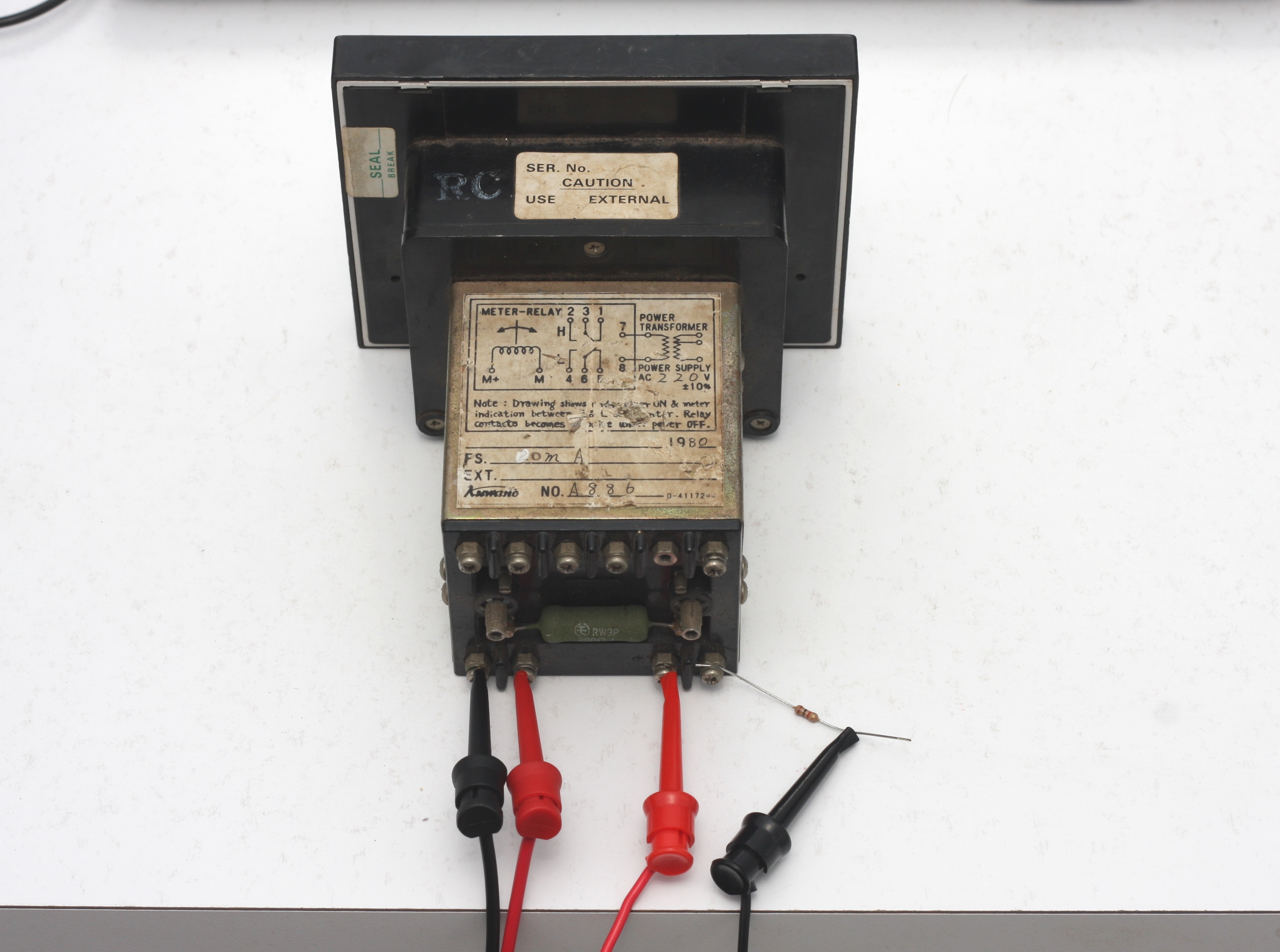
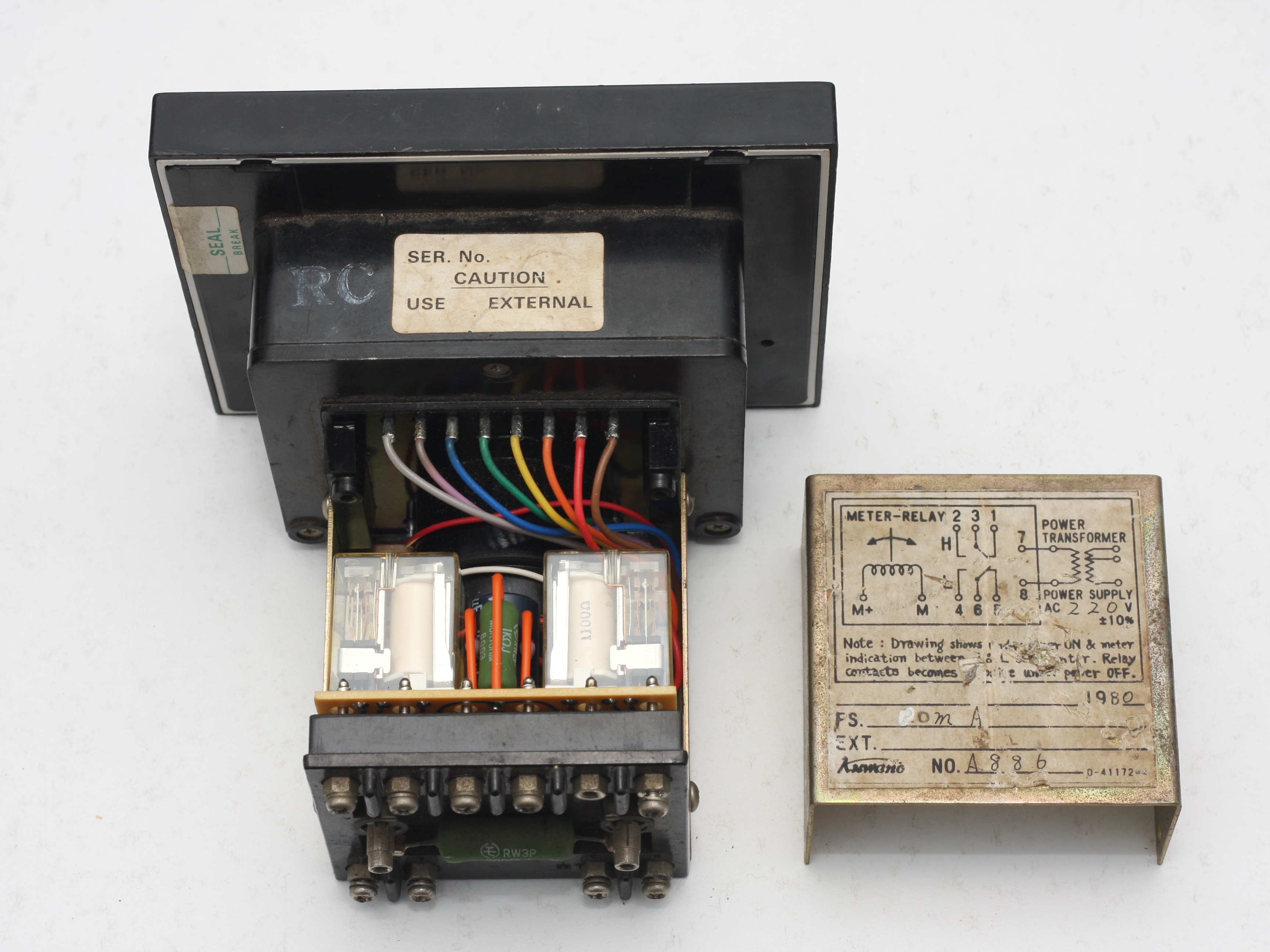
Below is a panel meter that has been used in some sort of industrial process. It was manufactured in 1980 by Kuwano. I’m not quite sure who the manufacturer was – the company’s logo is not easy to read but it might say, “Aumano”. What caught my attention with it was that it includes high and low needles as well as indicators and relay outputs for the high and low limits.

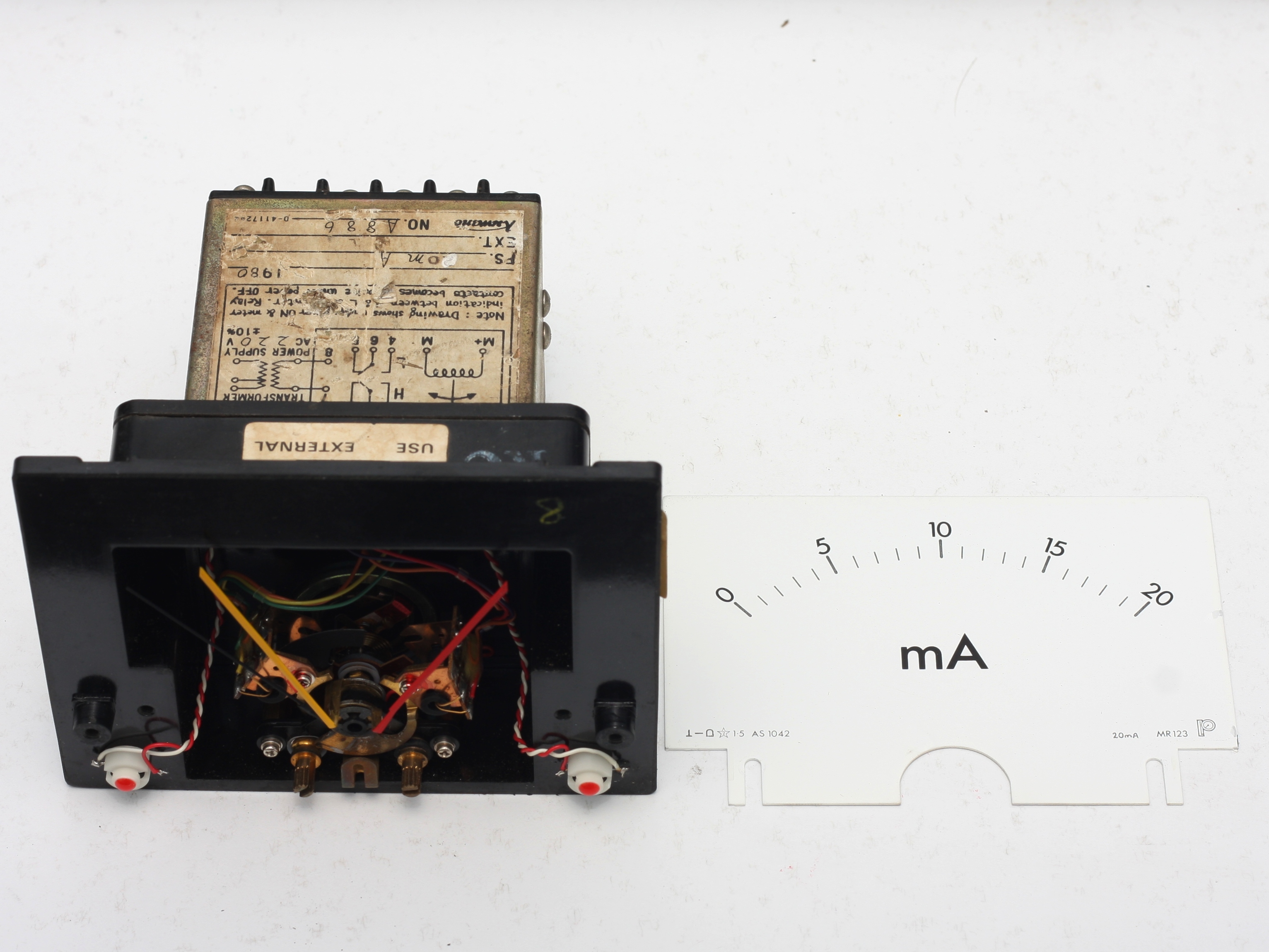
It’s scale is 0-20mA and the meter’s input is 0-20mA. This means the meter would have more than likely been used as the process indicator for a 4-20mA loop.
I don’t think I’ve written about 4-20mA control systems. The technology is old but it is a very robust and reliable technology and is still widely used today in modern industrial applications. I have seen 4-20mA control loops control some pretty critical processes (coke oven fuel control) and an entire lime kiln plant (from vibro-feeders pouring limestone into the kiln, through to the kiln rotation speed, oxygen to fuel ratio control and fuel burn rate. All with individual 4-20mA loops cascading into each loop) controlled using only 4-20mA control loops.
The concept of a 4-20mA current loop is the control signal is a varying current signal. Advantages of using current instead of voltage include; that it allows for very long cable runs (limited by the loop’s total resistance up to the system voltage), cable/interconnect resistance doesn’t affect signal accuracy and immunity to induced voltages (if you’ve ever had to design a weighing system with load cells you know how much of a pain this can be because the signal from the strain gauges is a low level mV signal). Another feature is the control signal’s low scale value is offset. That is, 4mA represents the low end of the scale instead of 0mA representing the low scale value. What this means, your control signal has a “live zero” and this allows you to differentiate between a physical failure in your control loop (such as a cable break or power supply failure) and a low scale reading.
Enough on the theory, does it still work? Yes, but is took a bit of cleaning. I managed to power it up and I could get the needle to respond to my crude current source of a 1k resistor in series with a variable power supply. However, the needle would get stuck at 8mA. Giving the meter a few gentle taps freed the needle. This is the likely reason I found the meter at a junk sale.
When the front bezel was removed, a fair amount of dust and dirt was found behind the bezel. The photo shows the dirt removed. I’m pretty sure this was the culprit for the sticky needle because after I gave the meter mechanism a clean with some gentle compressed air, the needle operates perfectly.

Behind the scale plate, the moving coil meter and min and max mechanisms can been seen.
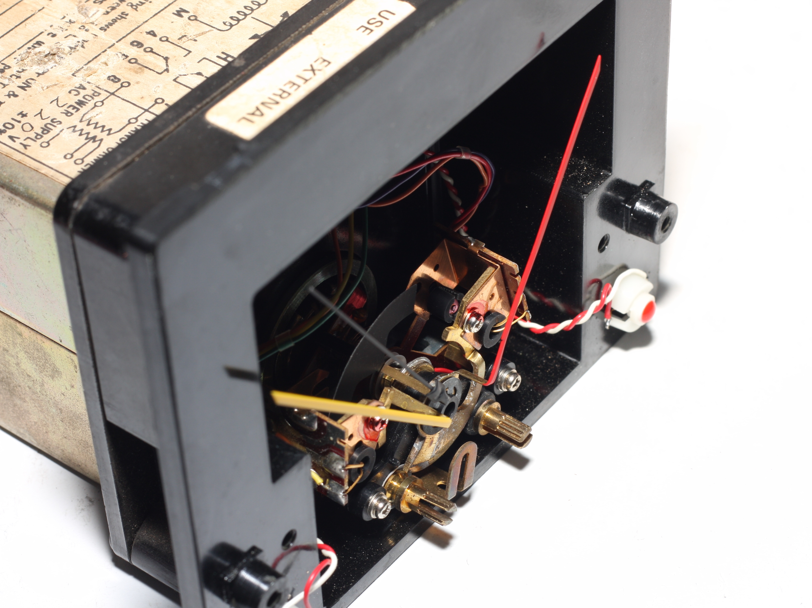
Adjustment of the min and max needles is performed with the knobs on the left and the right, respectively. A rubber o-ring on the knob’s shaft engages with the limit needle’s control arm.
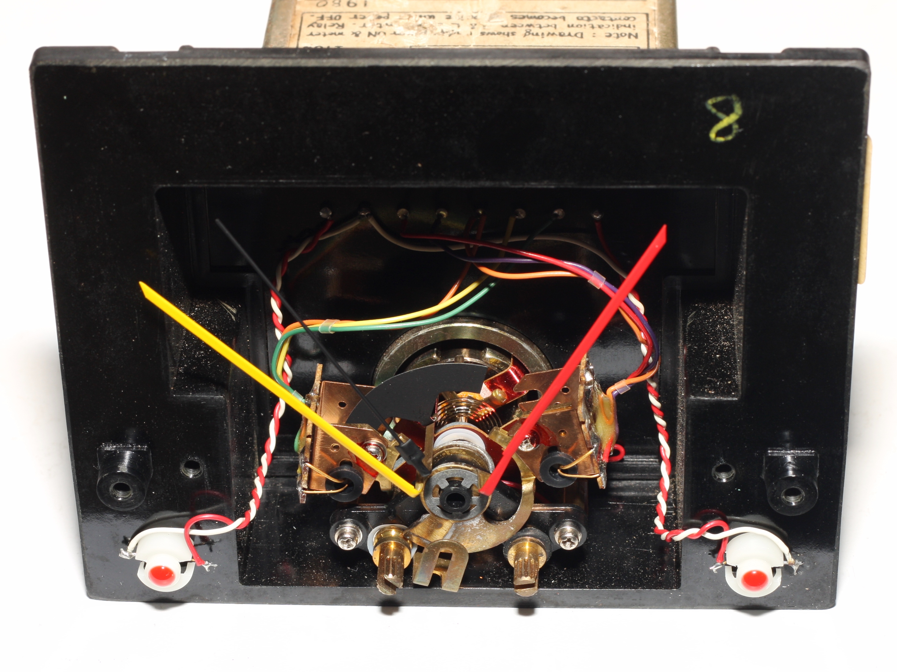
Activation of the min or max relay outputs is achieved by pairs of photo-interrupters mounted on the min and max needle assemblies. A shadow mask attached to the signal needle moves to block the photo-interrupter pair.
Removing the back cover reveals the min and max relays.
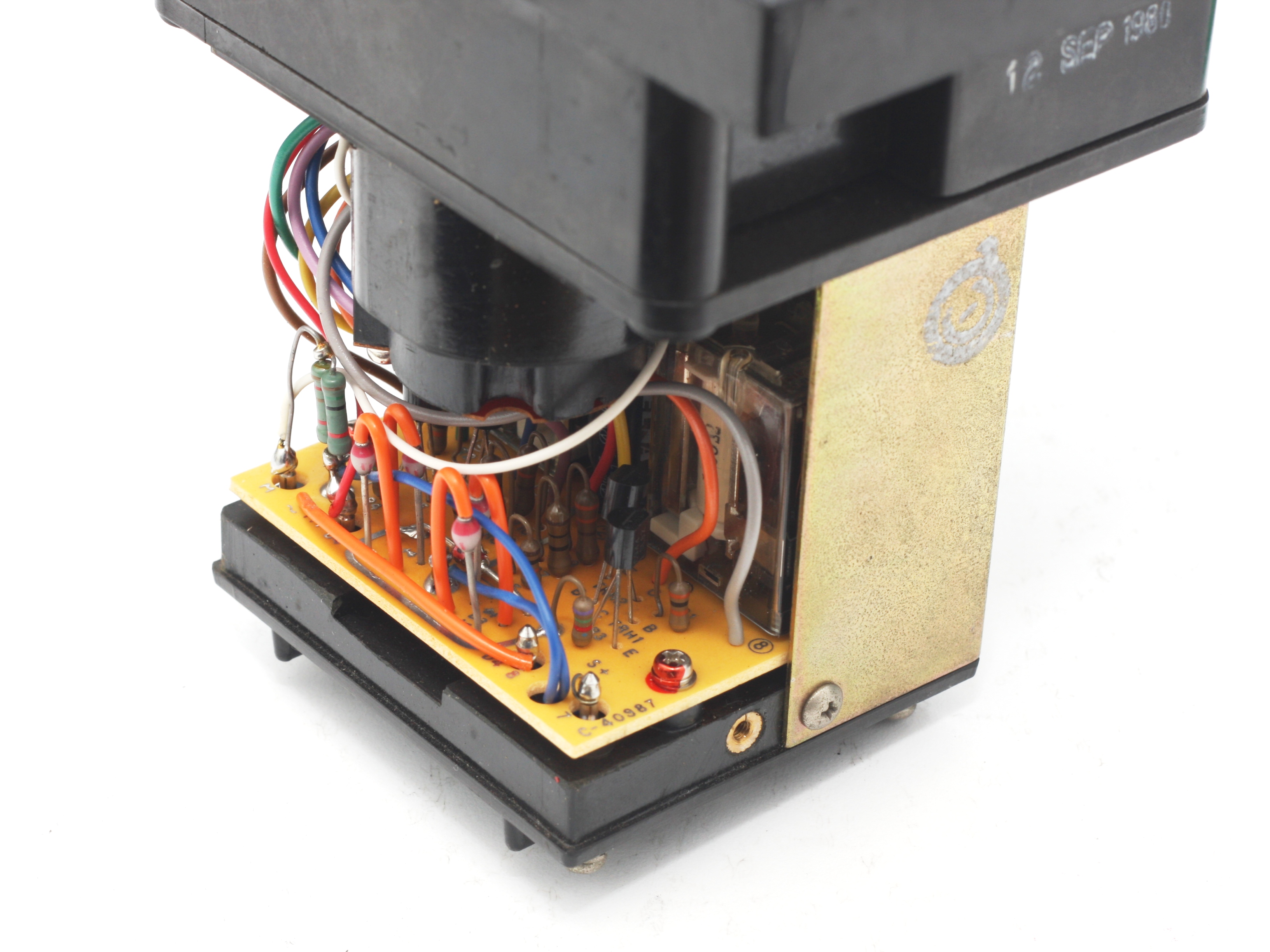
Removing the bottom rear cover reveals the analogue control wiring. Without tracing out the circuit, I can identify that the circuit has a full wave bridge rectifier and the remaining components would drive the photo-interrupter pair which in turn would control the relays and the front indicator LEDs. The quality of the workmanship is excellent – I’m sure this piece of hardware would have been quite expensive when bought.
Interestingly, the vertical resistors have insulated leads. When mounting resistors vertically, you need to be mindful of the resistor lead that is bent downwards, so it doesn’t short out on anything. However these resistors have been manufactured to have a portion of one of the legs insulated in the resistor body’s varnish.
Anyway, there’s not much else to say. Since cleaning out the dust, the meter works perfectly now. Maybe I might use the meter as an indicator in a project, such as a humidity or temperature display. If I do, I think it would be fitting to make the whole circuit analogue.

Kuwano
LikeLike
Thanks for your help J.S.
LikeLike