
Happy New Year everyone. A quick post to get the new year started and I recently scored a few HP5082-7340 hexadecimal LED display chips. These are cool looking integrated hexadecimal LED displays measuring 10mm wide and 14mm high with standard 2.54mm pin spacing.


A great feature of these displays is that each chip contains all the decoder and driver logic internal to the device. Unlike a Texas Instruments TIL302 which requires a BCD to 7-segment display driver chip such as a SN74LS47, the HP5082-7340 requires 5V, 4x pins for a BCD representation of the character, an enable signal and an optional display blanking signal.
Additionally, there is no need for current limiting resistors, this is handled on-chip.
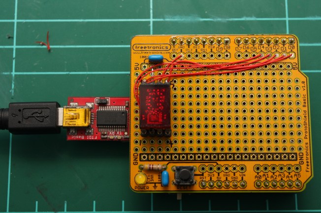
To demonstrate how the display looks, a quick breakout was made, a schematic of the circuit shows the simplicity of interfacing one of these display chips to a microcontroller.

A HP5082-7340 demo board was easily made within half an hour.
Only a few lines of code are needed to cycle through all the possible characters that the HP5082-7340 can display.
This post only demonstrates a single display chip operating. However, multiple HP5082-7340 chips working together to display larger strings of data is more practical. Soon, I’ll demonstrate how straightforward it is to operate multiple displays together simply using shift registers.
//www.steelcityelectronics.com
//
//Tim Hansen 2015
//
//Example display driver code for HP5082-7340 hexadecimal display
//

int pinEnable = 0;

int pinX1 = 1;
int pinX2 = 2;
int pinX4 = 3;
int pinX8 = 4;

int pinBlank = 5;

void setup() {

pinMode(pinEnable, OUTPUT);
pinMode(pinBlank, OUTPUT);

pinMode(pinX1, OUTPUT);
pinMode(pinX2, OUTPUT);
pinMode(pinX4, OUTPUT);
pinMode(pinX8, OUTPUT);
}

void loop() {
  for(int i=0; i<16; i++){  //loop through values 0 - 15.
    displayLogic(i);
    delay(200);
  }
}

bool displayLogic(byte numeric)
{
      if(numeric <0 || numeric >15){
       //This value can not be displayed. Return an error value of 0
        return 0;
      }
      else{
        digitalWrite(pinEnable, LOW);            //allow data to be latche din to the chip
        digitalWrite(pinX1, (numeric >> 0) & 1); //test if the LSB is a 1 or a 0.
        digitalWrite(pinX2, (numeric >> 1) & 1); //shift 1 place and test if bit is a 1 or a 0
        digitalWrite(pinX4, (numeric >> 2) & 1); //shift 2 places and test if bit is a 1 or a 0
        digitalWrite(pinX8, (numeric >> 3) & 1); //shift 3 places and test if bit is a 1 or a 0
        digitalWrite(pinEnable, HIGH);           //data pins are now set. Enable the chip to display the value
        return 1;                                //no error encountered.
      }
}

Nice post thaanks for sharing
LikeLike